DomotiGa, SmartVISU & Raspberry Pi

I’ve done it ! Finally completed installation of DomotiGa and SmartVISU. Below are only screenshots of draft setup as I still have to add some sensors and improvements, but it’s a start.

DomotiGa

DomotiGa


As DomogiGa is not directly compatible with GPIO ports (and since it’s installed on a different server anyway), my DomotiGa sensors are actually Shell devices which point to Python scripts (which connect to a MySQL DB and return the value of each sensor). Each Shell device gets automatically updated every 300 sec in DomotiGa by default, so to ensure I get live data I have added JSON-RPC calls in my GPIO script:

My GPIO Python script calls a bash file that contains the JSON-RPC Call:

curl -sS -X POST -H "Content-Type: application/json" -H "Accept: application/json" -d '{"jsonrpc": "2.0", "method": "device.set", "params": {"device_id": 2, "value": "On"}, "id": 2}' [server_ip_address]:9090

(I always send the value “On” but since DomotiGa will run the Python script following the JSON-RPC call it doesn’t matter)

My Python script for DomotiGa Shell Device:

import MySQLdb as mdb

con = mdb.connect(sqlhost, sqlusername, sqlpassword, sqltable)
cur = con.cursor()
cur.execute("SELECT pinStatus FROM pinStatus WHERE pinNumber=22")
row = cur.fetchone()
if(row[0] == '1'):
print "On"
else:
print "Off"
con.close()

My SmartVISU page contains this type of script for each device:

{{ basic.symbol('PIR1_Off', 'PIR1_switch', 'PIR 1', icon1~'message_presence.png', 0) }}{{ basic.symbol('PIR1_On', 'PIR1_switch', 'PIR 1', icon1~'message_presence_active.png', 1) }}


Domotiga

I’m planning (although at this stage it still more like dreaming) to take a major step in my setup: go away from the do-it-yourself / reinventing the wheel and start using a ready-made solution.
I spent some time looking around for an open-source solution. I was looking for something simple, with a web interface and narrowed down the contestants to 3: DomotiGa, Domoticz, Domogik.

I eventually made up my mind and chose DomotiGa as it seems the most versatile, robust and hardware compatible. I’m currently installing it on a Ubuntu box (the one on which this server is hosted).

And I’ve just found out a visually stunning interface called SmartVISU that can be plugged onto DomotiGa:

SmartVISU Screenshot

SmartVISU Screenshot

Watch this space 🙂


RPi HTML5 Control Panel

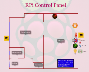
I wanted to improve the way I display the status of my sensors and decided to venture away from a simple table with icons and check out HTML5 for a more graphical display.

There are still a few tweaks to added:

  • Refreshing only the HTML canvas (drawings) rather than the whole page every 5 sec
  • At the moment only the CCTV and Temperature are, I need to add buzzer control

But for a proof of concept, I’m rather happy with the outcome.

RPi HTML5 Control Panel

RPi HTML5 Control Panel


Glade PIR – Update

I decided the “hacked” Glade PIR didn’t cut it.

  1. It responds to light conditions so a sudden change in lighting (sun & clouds) could trigger it
  2. It’s completely useless at night since without light it cannot detect movement linked to change in light conditions

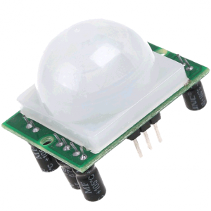
I therefore decided to buy another “real” PIR from Tandy. I however had a hole on the wall and all the wiring ready so I simply cut a whole in the Glade housing to fit the PIR.

PIR Motion Sensor Module

PIR Motion Sensor Module

Glade PIR V2

Glade PIR V2


LCD Brightness

The LCD display is stable enough for now that I don’t need to keep an eye on it (using a separate program to update it sorts any glitches out by re-initialising it).

However the brightness is just not right. The LCD was intended to be used with an Arduino board so expects +5V VDD, however it only receives a +3.3V VDD from the RPi.
Powering the LCD with +5V but using the +3.3V on I2C bus was not working.

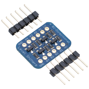
I’ve therefore purchased a Bi-directional Logic Level Converter (HERE), hoping to power the LCD with +5V and use the same voltage on the I2C bus at least at the LCD side:


4-channel Bi-directional Logic Level Converter

4-channel Bi-directional Logic Level Converter


I should hopefully set this up shortly and will update my findings here.


[Update – 30th Dec 2013]

The Logic Level Converter doesn’t do the trick. The LCD does not get recognised by the Pi. I’ve even tried to power it via a diode to drop the power support from 4.6V (read from a multimeter) down to 3.9V (0.7V loss via the diode), but the Pi still does not recognise it. I’m starting to think this is a poor LCD, but it can still be read when powered by +3.3V, even though it’s a bit dimmed.


[Update – 3rd Oct 2016]

I know I had many issues due to the breadboard as the LCD would even dim for half a second if a loud sharp noise was made close by. Since I have a Humble Pi, everything is a lot more stable, so I thought of revisiting the Logic Level Converter avenue, and it’s all up and running smoothly now 🙂

Oh and I’ve also got a custom case 3D printed, see this post for more info…

LCD with Logic Level Converter

LCD with Logic Level Converter


LCD Display

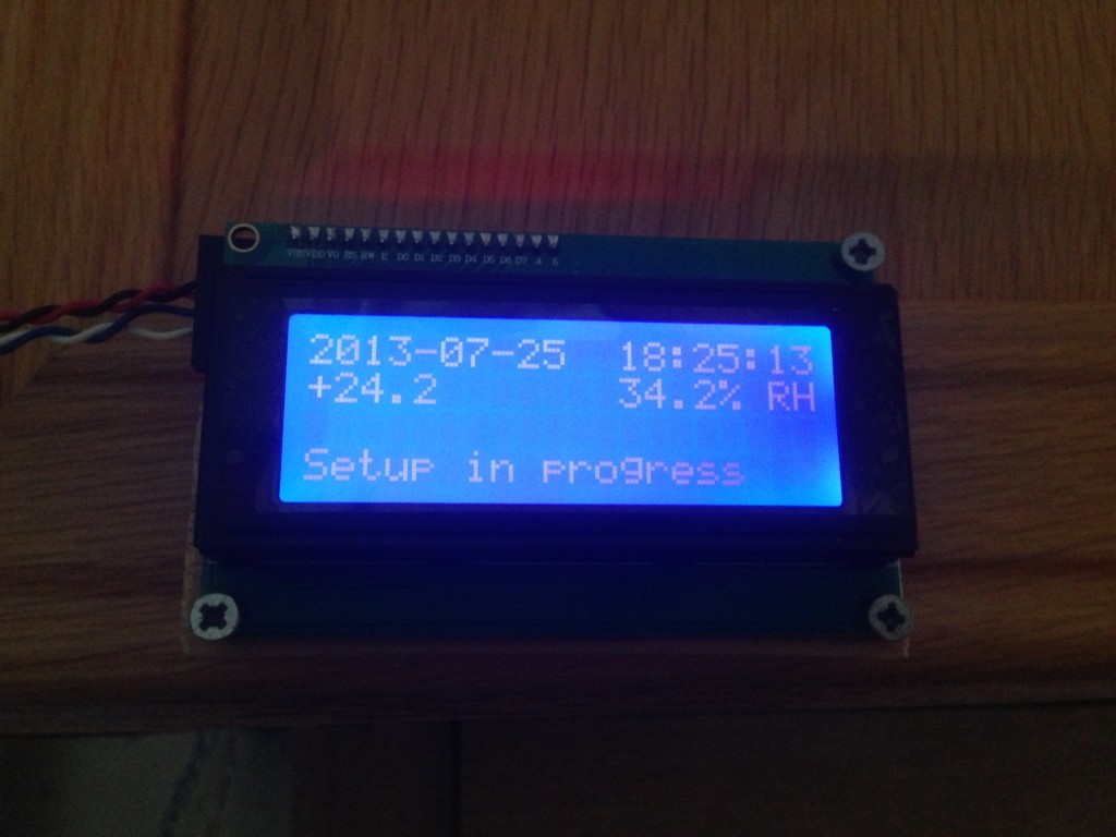
Until now the only way to check the status of some basic sensors (mainly the temperature) was to open the web interface I created.

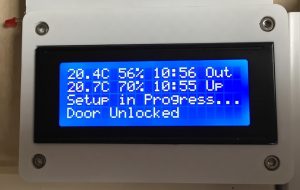
I wanted an easier and quicker way to check the temperature and humidity. I therefore decided to get a small LCD screen to display that basic info.

I ended up buying a SainSmart® IIC/I2C/TWI Serial 2004 20×4 LCD Module from Amazon.

2013-07-26 07.18.24Since I wanted to display data from different script sources (main GPIO controller script, Temperature and humidity script) I soon realised I had to use a separate script to handle the LCD as opposed to a simple call to display data: 2 simultaneous calls (or in quick succession) would scramble the I2C port and the LCD would either not display anything or display garbage.

I therefore use a MySQL database to hold the messages, which can be updated by any of my scripts, and a separate LCD.py handler that loops and updates the LCD

Note: the LCD’s address is 0x3F. You can confirm it’s correctly detected by running:

i2cdetect -y 0

or

i2cdetect -y 1

(depending on the version of your Raspberry Pi).

The LCD needs to be powered by +5V, but then it does not get detected:

pi@raspberrypi $ sudo i2cdetect -y 0
0 1 2 3 4 5 6 7 8 9 a b c d e f
00: -- -- -- -- -- -- -- -- -- -- -- -- -- 
10: -- -- -- -- -- -- -- -- -- -- -- -- -- -- -- -- 
20: -- -- -- -- -- -- -- -- -- -- -- -- -- -- -- -- 
30: -- -- -- -- -- -- -- -- -- -- -- -- -- -- -- -- 
40: -- -- -- -- -- -- -- -- -- -- -- -- -- -- -- -- 
50: -- -- -- -- -- -- -- -- -- -- -- -- -- -- -- -- 
60: -- -- -- -- -- -- -- -- -- -- -- -- -- -- -- -- 
70: -- -- -- -- -- -- -- --

I found that if I power the LCD with +3.3V it gets recognised but the display is a bit faint, even with the brightness set to max. A Logic Level Converter is then required to make it bright enough while being recognised. See the LCD Brightness post for more info on that…


DHT22 Crashing – “Resolved”

For some reason, the script I was running to get the temperature and relative humidity from the DHT22 kept hanging every so often.

Instead of running two scripts separately (one for the DHT22, one to monitor the other different sensors I have), I’m now calling the DHT22 script from my main script and in case the last update from the DHT22 is over 2 min old, I just kill it:

process = Popen(['sudo', 'killall', '-9', 'DHT.py'])

and restart it.

subprocess.Popen(['sudo',  './DHT.py'])

For the negative temperatures, the script seems ok, but since we’re in summer I have not had the chance to test why the returned data shows 0. I’ll have to wait for Winter for this one

Watch this space…


DHT Bug

I found out that the script from Adafruit to read the temperature and humidity levels out of the DHT22 has a bug: all negative temperatures return “0ºC”.

I’ve also experienced crashes every couple of days or so, I had a brief look at the code but it’s a tad too complex so I’ll have to crawl the web to see if I can find an alternative solution…


Look & Feel

For now I need to run a bash script to initialise the pin that drives the buzzer after reboot, then I can drive the buzzer by sending a HIGH command to the pin.

So while I iron out my script to correctly drive the buzzer, I thought I’d share a pic of what my setup currently looks like.
It’s still a work in progress, using a breadboard so it’s not pretty but still worth sharing 😉

2013-03-23_Pi_Setup (Large)


Temperature & Humidity Sensor

I’ve finally gone round to properly connecting my DHT22 sensor to my Raspberry Pi.
It’s actually been working fine for about 2 week, but as it was sitting on the breadboard on top of the Pi, the readings were not exactly accurate: it’s pretty warm and dry up there.
So today I moved the sensor outside to get real readings.

I’ve based my setup thanks to a tutorial on Adafruit. You can get it HERE

I’ve done a few changes though:

  • Based on the temperature and relative humidity readings, I’m calculating the dew point / frost point. The formula I used is this one:

    Dew point equation

    Dew point equation – Click for source website

  • I’m updating the readings to my SQL Database so I can use then on any page.
  • I’ve set up the readings to get added to an online Google spreadsheet only once per hour. The idea is to keep recording for as long as I can and then get some yearly trends. You can access the spreadsheet HERE